Idea: Helicopter with the blades extendeding from the outer edge of a lens shaped lifting body

I was today walking with a dog and it occurred to me that with a fly by wire system a helicopter which would have blades outside of a circular lifting body and that would have a pusher prop (cruise prop) on top of the said flat lifting body in a pivoting pylon with thrust vectoring, could possibly fly stable and avoid the not that good things of a helicopter and be more efficient VTOL craft than a conventional helicopter. The bearing on the outer ring would possibly though be some sort of a challenge. On a big one, the outer ring could be not connected to the inner ring at all, but it could actually use maglev technique to levitate in a hole without physical contact with the bearing. This could come with too heavy weight penalties, so not sure if it would be feasible. So this is just a out of the box thinking idea because I have always felt that there is something wrong with helicopters, I have never really liked how they look like and how they function, there must be a better way to do that.

Cyclic system could be hidden inside the center section so that it would not cause drag like on a helicopter where there are lots of mechanical parts directly in the airflow causing drag. In cruise the plane would be a gyrocopter rather than a helicopter because it would have positive angle of attack unlike helicopter which cruises at negative angle of attack (and only blades have positive angle of attack).

I would like to try this as RC-model, but the challenge would be to fabricate such a large and yet lightweight bearing that would be size of the craft itself. The outer shell with the bearing would have a gear tooth that would be driven with a pinion gear that would be connected to the engine. This would also function as gear reduction drive. In addition to the ring drive to takeoff and landing, there would need to be a generator for driving the pylon mounted thrust vectoring prop that would be run with an electric motor.

The shape of the lifting body would be a suboptimal airfoil because it would need to be symmetrical and have both sharp leading edge and trailing edge but. This kind of craft would be naturally unstable but it could be artificially stabilized with software.

Cross sections in Rhino from a loft

I wrote a long time ago about how to do cross sections in Rhino. I mentioned that it needs to be Object intersection. If you do Boolean Intersection, this technique is not going to work. I found that the earlier instruction might have been a bit confusing because there are multiple ways to do intersections in Rhino.

The original article is here: http://design-plane.blogspot.com/2020/10/irhino-learnings-of-today.htmlPlease read it.

The function what you have to use is Intersect (to do Object Intersection).
If you type it to the command area, type Intersect, not Intersection or Booleanintersection.
You know that you have chosen wrong intersection method if you have to select two set of objects. Multiselect everything (your cutters and the lofted surface) at the same time and do Intersect. It works.

Rutan Proteus photo collection

NASA has nice photo collection. If you like the looks of the Proteus (in my opinion it is one of the most beautiful aircraft ever done), have a look:
http://www.dfrc.nasa.gov/gallery/photo/Proteus/index.html

Airplane design from structural efficiency point of view combined with aerodynamics point of view - multi-domain optimization

So far I have been looking only the aerodynamics side, but it is quite evident that compromises are needed on the aerodynamics side to achieve the best structural efficiency. I think one good example is Virgin Global Flyer (Scaled Composites model 311). I have not analysed yet the structure, but common sense says that trimaran has weight placed more evenly along the wing span avoiding a very large point load in the middle where the single fuselage would normally exist. The trimaran may have more wetted area than a single fuselage, but on the other hand, weight savings in the very high aspect ratio wing and space gains for the extra fuel are in this concept very important factors.

I find the trimaran configuration quite interesting - several different engine placement configurations for example can be used with this configuration without changing the aerodynamic shape of the concept very much. It is also interesting because it allows placement of the main gear away from the center fuselage and thus provides greater stability on the ground when the aspect ratio is high even if there is fuel placed to the wings very far away from the center of gravity. And as can be seen the same design suits several different missions: Global Flyer is very much like White Knight 2 with SpaceShipTwo under it on the center. Almost the same configuration, adapted to different kind of mission for very different kind of parameters (Global Flyer = long range cruise, White Knight 2 = optimized for climb).

Global flyer drawing Google found from some site
Wikipedia has another great photo, this is from front

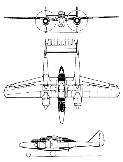
The configuration is not really so new and not so unproven either, as people might expect, here is one example where a similar configuration has been used a long time ago:
Northrop Widow
The only difference here is that the Northrop Widow was optimized for different mission than either of the abovementioned and that it had piston engines in front of the outer "fuselages" which were interconnected from the tail section similarly than in Adam A500 whereas the Global Flyer and White Knight Two have two separate tails. It is quite apparent why the tails are separate in these aircraft - because the outer fuselages are placed so widely apart from each other, connecting the tails would have made the tail unnecessarily large which would have caused negative effect for the drag despite it would have had fewer intersections. On the other hand, I have been looking different HALE concepts, and it is quite apparent that the number of intersections is not the major drag source in high altitude aircraft, but the induced drag is, and to minimize induced drag, more intersections can be allowed as the penalty from them is lesser than limiting the aspect ratio would be. This is why there are even some concepts considered at the moment which have wing struts - even if everybody knows that they produce drag, in some concepts, the significance of that drag can be proportionally small whereas the increased aspect ratio has major effect on minimizing the total drag of the aircraft. HALE aircraft have to be quite different than those which are designed to cruise at low altitude, the drag percentages of each contributors are quite different and "one size does not fit all".

It is quite interesting area to explore when the structural efficiency is added to the equation in addition to the aerodynamics and the result is a compromise on both structures and aerodynamics instead of being optimized for either aerodynamics or for structures. The mission parameters tend to heavily affect both and best suited results can be achieved by combining these two and by knowing the intended use exactly, potentially bigger gains can be realized than in a concept that is a general purpose in everything (GA = GENERAL aviation).

Austin's jet design

x-plane.com website had looked a bit boring lately, Austin's long and interesting changelogs are hidden deep under the menu structure, looks like a design of a web designer lately.

But luckily yesterday I realized that Austin had added a link on top of the page. Small link on top of the web designer blob and that goes directly into an interesting page. Now today there are two links (as there is 9.50 beta for X-plane available too), but this one was particularly interesting in the topic of this blog: The Laminar Research X-1 Cavallo is conceived

Why Diamond uses Wortmann FX63-137?

I have been thinking over and over again why Diamond has chosen the Wortmann high lift airfoil FX63-137 on its aircraft. However, I am suspecting what might be the reason (not confirmed though since anybody on Diamond booth e.g. in Oshkosh is usually never able to answer to my questions). Here is my theory about it:
- The FX63-137 has high L/D at fairly high alpha and thus Cl (as the airfoil is such that the Cl rises rapidly as a function of alpha). This is maybe not the best configuration for cruise where a low drag bucket at low Cl is desirable. On an airfoil which has best L/D at low Cl, the climb has more D component (because high lift devices cause drag) and while getting more L with high lift devices. It might be close to the optimal climb optimisation on the chosen aspect ratio on those planes and compromise is drawn to cruise and it is not seen as a bad thing because competition is not faster but usually slower, it does not take so much to win e.g. a C172 in efficiency and speed after all. So it might be that with a lower drag cruise airfoil e.g. DA42NG with the very heavy diesel engines might have somewhat poorer climb rate on single engine situation or it might not climb alltogether if the airfoil was not optimised to provide low drag on high Cl.
- Comparison between the DA40 and Cirrus SR20 kind of potentially shows this: the Diamond shows significantly better climb rates with a quite similar AR and quite similar wing loading (SR20 takes some toll on that, but not that much in comparison if a light loaded SR20 and heavy loaded DA40 is compared), despite of the fact that the SR20 has more sophisticated flaps and the SR20 has 20 hp more engine power available.
- This can be also evidenced on best climb rate speed: with similar wing loading, the best climb rate speed is much higher on the SR20 than it is on the DA40, which partly indicates that the sweet point in the L/D occurs at lower alpha on SR20 than on DA40. SR20 also requires quite accurate angle of attack and thus speed to climb optimally whereas the DA40 is not that critical which would also indicate that the low drag bucket of the FX63-137 is broader than on the (according to UIUC data site) Roncz airfoil on the SR20.

So this is just my home-brewn theory style thinking, is based on collected information and my experience with flying the Diamond DA40, DA42 and Cirrus SR20 and SR22. I might be wrong as always, but here is some food of thought if you have been thinking why there is this airfoil with high L/D at high Cl and the airfoil also has fairly high pitching moment which some find undesirable because of for example trim drag.

Powerful electric motors

I found this one for example:

Turnigy CA120-70 Brushless Outrunner (100cc eq)

With two of these a small single seater would fly quite easily.

Blog Archive