New variant of the shape I have been thinking about

Here is my today's result from iRhino:


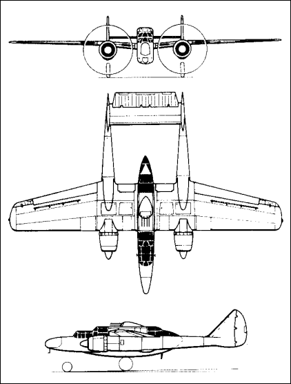
The idea is that the fuselage center section blends into wings like on blended wing body, but it only forms a minor portion of the shape, high aspect ratio wings continue from the blended part and there is a tail in the rear. I have not drawn this as I was thinking because I have been thinking either V-tail or T-tail. This picture doesn't yet have a rudder.

Now the difficulty is that I have hard time on getting the Rhino do what I think. The loft is challenging, because it follows airfoil shape, it follows the configuration and contour from the top I was thinking, but the problem is to vary the airfoil shape in the center section so that the transition from the right side to the left side is smooth and more circular than in this thing where it is pretty sharp (the sharpness there is completely unintentional and will go away as soon as I figure how to loft this thing properly).

The wing tips did not loft as I planned, and also the elevator has wrong airfoil shape in the tip, the scale2D produced results I was not planning to get. There is still something to learn in Rhino. I need to ask from maybe Jani tomorrow how to do this right.

X-plane as educational program

It seems that X-plane educates aerodynamics, what to expect and think about different things. I was originally saying that I am not so interested in transonic region but rather interested in high altitude. I have been reading about these, but some little things like tinkering with X-plane can cause heureka moments.

And here is what happened:
I have a model of my twin concept in X-plane simulator (obviously, why wouldn't I). So I set in the latest incarnation the engine critical altitude to 50000 ft (which is feasible with two turbos in cascade plus the mentioned electric turbo compounding). I used 110 hp per side (equivalent of Rotax 912ULS equipped with two turbos doing turbo normalization plus intercooler and after cooler).

I was reading Roskam couple of days ago and noticed that the transonic drag is not a problem if the speed is mach 0.2 or below or not that much above that, e.g. 0.3-0.4 is still quite fine. So I was thinking that maybe it doesn't get that high that it would become a consideration.

So so obviously, I put the plane model to climb to 55000 ft with autopilot. I had previously added the mach meter to the hud. I came back checking how it flies after couple of tens of minutes. And oops: mach 0.56 when level at 55000 ft. The IAS was barely 100 kts. TAS was a quite a bit higher.

Then, I was thinking what happens to the Reynolds number. Indeed it gets smaller with altitude increasing. But interesting thing is what really happens, to which number it gets. I verified with atmosphere calculator, that indeed, the interesting Re range for this kind of concept with the AR=14 wing, it becomes 600000 - 1600000. That is _very_ low for an aircraft, which is full size and not a RC-model. So the low Re becomes after all a major consideration.

How a plane with AR=14 flies at 55000 ft? It requires _full_ trim aft (meaning nose high) to get the plane keep level - in this model. It became quite apparent that indeed, the tail volume coefficient is a more major concern at high altitude than at low altitude. And the control authority that felt fine at low altitude was not so fine at high altitude.

So this is what we have:
- High performance low Re airfoil is very necessary
- Cd at high lift coefficient is an important design point, the airfoil needs to be designed so that it gives high L/D at high lift coefficient rather than at low lift coefficient like for example NLF414F is targeting.
- A big tail with long enough moment arm
- Propeller with large diameter and possibly more blades than usual, e.g. 5 blades
- And of course, two turbos, intercooler, aftercooler, generator, battery, electric motor and a shaft between the prop and the engine.

Btw, my model is not yet available for download because it is not perfect, and it has couple of problems. It is very hard to get the splines right with straight sections edited by hand, and e.g. engine nacelles look really terrible at the moment. Anyway, it is a fun way for trying out things in practice.

Boom tail microlight/LSA

I was thinking which could be a suitable configuration if target would be to the microlight category (Finnish ultralight will be aligned with European microlight), or to EASA LSA category. The US-LSA category is stupid since it has some severe limitations which removes the reason to try to optimize anything - the speed limitation and also the stall speed limitation as clean -> with these limitations, it does not worth optimizing the aerodynamic performance or flap configuration, for US-LSA, the best solution probably would to design a plane, which is as lightweight as possible and which would not have any kind of flaps and which would achieve the stall speed only with the wing area (because that is what the limitation implies anyhow), so the utilized Clmax becomes close to 1.0, which is poor.

The main criteria in this more sane European category is the weight and the second main criteria is the stall speed. These are the most important features, other features are secondary. The performance can not be optimal, but it can be optimized to the constraints given by the weight and stall speed limitations. It would be also necessary to cut the part count to minimum, an inexpensive plane will be for sure more popular than the more expensive one, in the category where the buyers are not the richest people out there (who would anyhow order a Cirrus-Jet), but normal hobbyists who are not swimming in money.

So consider this:
- Plane structure would be based on carbon fiber rods (pultrusion rods).
- The fuselage would not be a structural member of the plane, but rather a baggage pod located below the spars. The twin booms would be a pultrusion rod each. The engine would be mounted to the wing spar rather than to the fuselage. These rods could have aerodynamic fairings on top of them (which also allow space for control cables etc.).
- high aspect ratio wing, which enables good climb rate with low power
- HKS700E engine in pusher configuration
- Fixed pitch pusher propeller behind the pod (but thrust line to the wing spar).
- inverted V-tail in the ends of the two booms, and the tail would connect the
two booms with the help of a pultrusion rod which functions as spar.
- Main landing gear connected to wing spar
- Nose gear located under the pod.
- Wing structure would be solid blue styrofoam, and in wing root there would be a large fairing which contains fuel (on both sides). The wing skin could be either carbon fiber or fiberglass (fiberglass to reduce cost obviously)

Think how many parts this requires compared to how many parts and layup schedules is usually needed. The pod type cockpit could be almost a complete monococue. There would be need for only instrument panel and some structure where one can assemble the pedals. Also the instrument panel, as we know it, does not need to be like it is, a panel. There are other ways arranging instruments in the plane than having a straight panel where everything is put with tiny screws. None of the modern cars use that old-fashioned way anymore. With modern avionics, you don't need a big panel with lots of switches, knobs, circular gauges etc. You can have just two screens which display and control everything.

The only strength needed in the fuselage is for crashworthiness, it does not need to carry any loads, and it does not need to be shaped unoptimally to avoid flutter tendency for example, all structural members are straight lines and separate from the fuselage.

The idea comes from some NASA PAV concepts, but as modified. It also has some influences from the Sunseeker.

The concept could have idea of being as lightweight as possible (the lower power engine also supports this mission) and still being as highly performing as possible (that can be achieved with the light weight and aerodynamics, not so much trust is needed).

So the performance target setting for conceptual design could be:
- beat 100 hp Dynaero MCR-ULC in empty weight with large margin
- be on par with 100 hp Dynaero MCR-ULC in speed (with only 60% of the power available)
- and the rest comes from the category limitations
- be a lot cheaper than most other same category plane on the market
- climb rate 800 fpm (remember that because of the low climb speed, the climb gradient is high despite of the not so high number compared to high performance aircraft)

Compromise:
- beat 100 hp Dynaero MCR-ULC in empty weight
- cruise speed compromised to between 80 hp WT9 Dynamic and 80 hp MCR.
- climb rate 600 fpm

Failure:
- heavier than MCR-ULC
- slower than 100 kts in cruise
- climb rate less than 500 fpm

Anyone interested in a such thing or having ideas (for or against) for a such thing?

Here is an illustration about the idea (15 minutes of Rhino magic):

6 milestones plan for getting things done

I have been thinking the ways to achieve a design and implementation of a dream aircraft, and have concluded that it has to go in more than one step, so I was thinking the following milestones:

1. Unpressurized version, with a single turbo and fuel injection kit per engine. Possibly with a cabin similar to seen in Orka, avoid the manufacture of the doors. Woodcomp CS propellers. Target cruise altitude = 25000-30000 ft with supplemental oxygen. Corners cut where necessary to just get it done. No active boundary layer control, no wing tip propellers etc., rely on natural laminar flow to achieve efficiency. Unstable release of plans, calculations etc. Version A.
2. Open source plans stable release for the version A (CNC code, 3D models, 2D drawings, construction plans, layup schedules). Flight testing gives the final specifications for version B and ideas what to change to version B. Version A prototype is in use.
3. Optimized version of the above, version B. Modifications to version A prototype, version A becomes version B.
4. Stable release of version B plans (CNC code, 3D models, 2D drawings, construction plans, layup schedules). Version B might be alternative for a basis of a kit.
5. Pressurized version with doors, twin turbos per engine, intercooler and aftercooler per engine, computer controlled waste gates, and hybrid turbo compounding with two electric motors where one is functioning as generator and the the other runs the compounding. Possibly longer wings for high altitude flight. MT propeller or other higher end propellers. Possibly aerodynamic design changes, based on issues found in versions A and B and other improvements. Version C.
6. Open source plans stable release for the version C (CNC code, 3D models, 2D drawings, construction plans, layup schedules). Version C is a completely new aircraft and thus version B and version C coexists.

There are at least two milestones before 1.
-1 = concepting and collecting information, and creating needed softwares (present)
0 = initial concepting freezes, and version control repository (e.g. svn) exists for all data and there is a web page for the project.

Focusing and streamlining my concepts into 5 steps or tiers

I have apparently so many ideas that they can not be incorporated in one aircraft. Therefore I have concluded that there needs to be several steps or tiers with a slightly different themes.

So these are now:
Tier 1: Conventional simplicity: Low drag low power low cost twin. Small wing but high aspect ratio. Compromise: Medium power to weight ratio required. Concept usable for personal aviation.
Potential outcomes: RC-models, UAVs, Private aircraft.
Budget: Shoe-string

Tier 2: Flying wing: Suitable for diesel power, series hybrid and other non-optimal power/weight ratio powerplants. Large wing. Compromise: Poor power to weight ratio is ok.
Potential outcome: Plane with long range and diesel economy. UAV applications possible.
Budget: Shoe-string, external funding possibly needed for the large craft

Tier 3: Ladder: Large aspect ratio, climb machine. Compromise: High power to weight ratio beneficial, has impact in fuel consumption. Interference drag from multi-fuselage configuration.
Budget: External funding required. Implementation requires substantial investments in infrastructure and machinery.

Tier 4: Scissor wing delta: Aircraft that are optimized for speed and altitude.
Budget: Requires substantial investments.

Tier 5: Will happen only if tier 1-4 succeed. Idea not announced. Not all of these will be guaranteed to produce real flying aircraft, these are just categorization for a family of concepts.

Airplane design from structural efficiency point of view combined with aerodynamics point of view - multi-domain optimization

So far I have been looking only the aerodynamics side, but it is quite evident that compromises are needed on the aerodynamics side to achieve the best structural efficiency. I think one good example is Virgin Global Flyer (Scaled Composites model 311). I have not analysed yet the structure, but common sense says that trimaran has weight placed more evenly along the wing span avoiding a very large point load in the middle where the single fuselage would normally exist. The trimaran may have more wetted area than a single fuselage, but on the other hand, weight savings in the very high aspect ratio wing and space gains for the extra fuel are in this concept very important factors.

I find the trimaran configuration quite interesting - several different engine placement configurations for example can be used with this configuration without changing the aerodynamic shape of the concept very much. It is also interesting because it allows placement of the main gear away from the center fuselage and thus provides greater stability on the ground when the aspect ratio is high even if there is fuel placed to the wings very far away from the center of gravity. And as can be seen the same design suits several different missions: Global Flyer is very much like White Knight 2 with SpaceShipTwo under it on the center. Almost the same configuration, adapted to different kind of mission for very different kind of parameters (Global Flyer = long range cruise, White Knight 2 = optimized for climb).

Global flyer drawing Google found from some site
Wikipedia has another great photo, this is from front

The configuration is not really so new and not so unproven either, as people might expect, here is one example where a similar configuration has been used a long time ago:
Northrop Widow
The only difference here is that the Northrop Widow was optimized for different mission than either of the abovementioned and that it had piston engines in front of the outer "fuselages" which were interconnected from the tail section similarly than in Adam A500 whereas the Global Flyer and White Knight Two have two separate tails. It is quite apparent why the tails are separate in these aircraft - because the outer fuselages are placed so widely apart from each other, connecting the tails would have made the tail unnecessarily large which would have caused negative effect for the drag despite it would have had fewer intersections. On the other hand, I have been looking different HALE concepts, and it is quite apparent that the number of intersections is not the major drag source in high altitude aircraft, but the induced drag is, and to minimize induced drag, more intersections can be allowed as the penalty from them is lesser than limiting the aspect ratio would be. This is why there are even some concepts considered at the moment which have wing struts - even if everybody knows that they produce drag, in some concepts, the significance of that drag can be proportionally small whereas the increased aspect ratio has major effect on minimizing the total drag of the aircraft. HALE aircraft have to be quite different than those which are designed to cruise at low altitude, the drag percentages of each contributors are quite different and "one size does not fit all".

It is quite interesting area to explore when the structural efficiency is added to the equation in addition to the aerodynamics and the result is a compromise on both structures and aerodynamics instead of being optimized for either aerodynamics or for structures. The mission parameters tend to heavily affect both and best suited results can be achieved by combining these two and by knowing the intended use exactly, potentially bigger gains can be realized than in a concept that is a general purpose in everything (GA = GENERAL aviation).

Austin's jet design

x-plane.com website had looked a bit boring lately, Austin's long and interesting changelogs are hidden deep under the menu structure, looks like a design of a web designer lately.

But luckily yesterday I realized that Austin had added a link on top of the page. Small link on top of the web designer blob and that goes directly into an interesting page. Now today there are two links (as there is 9.50 beta for X-plane available too), but this one was particularly interesting in the topic of this blog: The Laminar Research X-1 Cavallo is conceived

X-plane as educational program

It seems that X-plane educates aerodynamics, what to expect and think about different things. I was originally saying that I am not so interested in transonic region but rather interested in high altitude. I have been reading about these, but some little things like tinkering with X-plane can cause heureka moments.

And here is what happened:
I have a model of my twin concept in X-plane simulator (obviously, why wouldn't I). So I set in the latest incarnation the engine critical altitude to 50000 ft (which is feasible with two turbos in cascade plus the mentioned electric turbo compounding). I used 110 hp per side (equivalent of Rotax 912ULS equipped with two turbos doing turbo normalization plus intercooler and after cooler).

I was reading Roskam couple of days ago and noticed that the transonic drag is not a problem if the speed is mach 0.2 or below or not that much above that, e.g. 0.3-0.4 is still quite fine. So I was thinking that maybe it doesn't get that high that it would become a consideration.

So so obviously, I put the plane model to climb to 55000 ft with autopilot. I had previously added the mach meter to the hud. I came back checking how it flies after couple of tens of minutes. And oops: mach 0.56 when level at 55000 ft. The IAS was barely 100 kts. TAS was a quite a bit higher.

Then, I was thinking what happens to the Reynolds number. Indeed it gets smaller with altitude increasing. But interesting thing is what really happens, to which number it gets. I verified with atmosphere calculator, that indeed, the interesting Re range for this kind of concept with the AR=14 wing, it becomes 600000 - 1600000. That is _very_ low for an aircraft, which is full size and not a RC-model. So the low Re becomes after all a major consideration.

How a plane with AR=14 flies at 55000 ft? It requires _full_ trim aft (meaning nose high) to get the plane keep level - in this model. It became quite apparent that indeed, the tail volume coefficient is a more major concern at high altitude than at low altitude. And the control authority that felt fine at low altitude was not so fine at high altitude.

So this is what we have:
- High performance low Re airfoil is very necessary
- Cd at high lift coefficient is an important design point, the airfoil needs to be designed so that it gives high L/D at high lift coefficient rather than at low lift coefficient like for example NLF414F is targeting.
- A big tail with long enough moment arm
- Propeller with large diameter and possibly more blades than usual, e.g. 5 blades
- And of course, two turbos, intercooler, aftercooler, generator, battery, electric motor and a shaft between the prop and the engine.

Btw, my model is not yet available for download because it is not perfect, and it has couple of problems. It is very hard to get the splines right with straight sections edited by hand, and e.g. engine nacelles look really terrible at the moment. Anyway, it is a fun way for trying out things in practice.

Boom tail microlight/LSA

I was thinking which could be a suitable configuration if target would be to the microlight category (Finnish ultralight will be aligned with European microlight), or to EASA LSA category. The US-LSA category is stupid since it has some severe limitations which removes the reason to try to optimize anything - the speed limitation and also the stall speed limitation as clean -> with these limitations, it does not worth optimizing the aerodynamic performance or flap configuration, for US-LSA, the best solution probably would to design a plane, which is as lightweight as possible and which would not have any kind of flaps and which would achieve the stall speed only with the wing area (because that is what the limitation implies anyhow), so the utilized Clmax becomes close to 1.0, which is poor.

The main criteria in this more sane European category is the weight and the second main criteria is the stall speed. These are the most important features, other features are secondary. The performance can not be optimal, but it can be optimized to the constraints given by the weight and stall speed limitations. It would be also necessary to cut the part count to minimum, an inexpensive plane will be for sure more popular than the more expensive one, in the category where the buyers are not the richest people out there (who would anyhow order a Cirrus-Jet), but normal hobbyists who are not swimming in money.

So consider this:
- Plane structure would be based on carbon fiber rods (pultrusion rods).
- The fuselage would not be a structural member of the plane, but rather a baggage pod located below the spars. The twin booms would be a pultrusion rod each. The engine would be mounted to the wing spar rather than to the fuselage. These rods could have aerodynamic fairings on top of them (which also allow space for control cables etc.).
- high aspect ratio wing, which enables good climb rate with low power
- HKS700E engine in pusher configuration
- Fixed pitch pusher propeller behind the pod (but thrust line to the wing spar).
- inverted V-tail in the ends of the two booms, and the tail would connect the
two booms with the help of a pultrusion rod which functions as spar.
- Main landing gear connected to wing spar
- Nose gear located under the pod.
- Wing structure would be solid blue styrofoam, and in wing root there would be a large fairing which contains fuel (on both sides). The wing skin could be either carbon fiber or fiberglass (fiberglass to reduce cost obviously)

Think how many parts this requires compared to how many parts and layup schedules is usually needed. The pod type cockpit could be almost a complete monococue. There would be need for only instrument panel and some structure where one can assemble the pedals. Also the instrument panel, as we know it, does not need to be like it is, a panel. There are other ways arranging instruments in the plane than having a straight panel where everything is put with tiny screws. None of the modern cars use that old-fashioned way anymore. With modern avionics, you don't need a big panel with lots of switches, knobs, circular gauges etc. You can have just two screens which display and control everything.

The only strength needed in the fuselage is for crashworthiness, it does not need to carry any loads, and it does not need to be shaped unoptimally to avoid flutter tendency for example, all structural members are straight lines and separate from the fuselage.

The idea comes from some NASA PAV concepts, but as modified. It also has some influences from the Sunseeker.

The concept could have idea of being as lightweight as possible (the lower power engine also supports this mission) and still being as highly performing as possible (that can be achieved with the light weight and aerodynamics, not so much trust is needed).

So the performance target setting for conceptual design could be:
- beat 100 hp Dynaero MCR-ULC in empty weight with large margin
- be on par with 100 hp Dynaero MCR-ULC in speed (with only 60% of the power available)
- and the rest comes from the category limitations
- be a lot cheaper than most other same category plane on the market
- climb rate 800 fpm (remember that because of the low climb speed, the climb gradient is high despite of the not so high number compared to high performance aircraft)

Compromise:
- beat 100 hp Dynaero MCR-ULC in empty weight
- cruise speed compromised to between 80 hp WT9 Dynamic and 80 hp MCR.
- climb rate 600 fpm

Failure:
- heavier than MCR-ULC
- slower than 100 kts in cruise
- climb rate less than 500 fpm

Anyone interested in a such thing or having ideas (for or against) for a such thing?

Here is an illustration about the idea (15 minutes of Rhino magic):

6 milestones plan for getting things done

I have been thinking the ways to achieve a design and implementation of a dream aircraft, and have concluded that it has to go in more than one step, so I was thinking the following milestones:

1. Unpressurized version, with a single turbo and fuel injection kit per engine. Possibly with a cabin similar to seen in Orka, avoid the manufacture of the doors. Woodcomp CS propellers. Target cruise altitude = 25000-30000 ft with supplemental oxygen. Corners cut where necessary to just get it done. No active boundary layer control, no wing tip propellers etc., rely on natural laminar flow to achieve efficiency. Unstable release of plans, calculations etc. Version A.
2. Open source plans stable release for the version A (CNC code, 3D models, 2D drawings, construction plans, layup schedules). Flight testing gives the final specifications for version B and ideas what to change to version B. Version A prototype is in use.
3. Optimized version of the above, version B. Modifications to version A prototype, version A becomes version B.
4. Stable release of version B plans (CNC code, 3D models, 2D drawings, construction plans, layup schedules). Version B might be alternative for a basis of a kit.
5. Pressurized version with doors, twin turbos per engine, intercooler and aftercooler per engine, computer controlled waste gates, and hybrid turbo compounding with two electric motors where one is functioning as generator and the the other runs the compounding. Possibly longer wings for high altitude flight. MT propeller or other higher end propellers. Possibly aerodynamic design changes, based on issues found in versions A and B and other improvements. Version C.
6. Open source plans stable release for the version C (CNC code, 3D models, 2D drawings, construction plans, layup schedules). Version C is a completely new aircraft and thus version B and version C coexists.

There are at least two milestones before 1.
-1 = concepting and collecting information, and creating needed softwares (present)
0 = initial concepting freezes, and version control repository (e.g. svn) exists for all data and there is a web page for the project.

New variant of the shape I have been thinking about

Here is my today's result from iRhino:


The idea is that the fuselage center section blends into wings like on blended wing body, but it only forms a minor portion of the shape, high aspect ratio wings continue from the blended part and there is a tail in the rear. I have not drawn this as I was thinking because I have been thinking either V-tail or T-tail. This picture doesn't yet have a rudder.

Now the difficulty is that I have hard time on getting the Rhino do what I think. The loft is challenging, because it follows airfoil shape, it follows the configuration and contour from the top I was thinking, but the problem is to vary the airfoil shape in the center section so that the transition from the right side to the left side is smooth and more circular than in this thing where it is pretty sharp (the sharpness there is completely unintentional and will go away as soon as I figure how to loft this thing properly).

The wing tips did not loft as I planned, and also the elevator has wrong airfoil shape in the tip, the scale2D produced results I was not planning to get. There is still something to learn in Rhino. I need to ask from maybe Jani tomorrow how to do this right.

Trying out different configuration layout for the twin concept


I decided to post here a snapshot of one of my Rhino-models. It has now struts which hold the engines out of the wing surface. The canopy was also replaced with windows.


Podrel

A funny idea came into my mind. There are couple of Petrel Amphibians in Finland. It looks like a plane of Donald Duck.

Here is one discussion thread in Finnish about it:
Nyt on suomen kolmas akuankkakone valmis

It has staggered wings (two wings, one on top of each other). What if it was completely different. Not exactly completely, but quite completely. Now on this latest Super Petrel, the engine pod is integrated to the upper wing. How if the upper wing was the only wing on the plane, the lower wing would not exist, the upper wing would be twice as long. The tail would not be angled upwards from the bottom of the fuselage, but it would be rather connected with two booms to the wing, in similar manner than it has been done on Adam A500. And finally, but not least, what if the fuselage was not a traditional fuselage, but a pod in the end of a strut, that fits the occupants, and nothing more. It would end before the prop arc. This would allow moving the propeller a bit downwards.

So the result:
- no aerodynamic penalty normally associated with the amphibian planes.
- center of thrust is at the same level as is the lift (high wing)
- because of the boom tail, the tail does not hit the water unless the plane flips.
- because you would not need to fit the tail to the fuselage, the fuselage-pod could be made a better boat shape

I could not resist, but name this idea as Podrel. Actually this is not a new idea entirely, it is partially borrowed from a NASA tech paper, but the application to amphibian use could be new twist for the configuration.

What do you think about this?

Twin engine concept, evolved from the single engine concept

Here is what I lofted today in the iRhino:


To make reasonable place for the rear seat/seats, the wing position had to be moved lowish position. The feet of the rear passengers are below the wing spar of the wing.
The rear window is not necessarily in the best place, it might be too much forward. The idea is that the rear seat ends before the prop arc.

The single engine idea in the previous post had apparent CG issues, how to get CG to correct position other than moving the prop completely on top of the fuselage, which moved the engine pod very high. This twin engine version which places the engine pods to the wings, solves this issue obviously.

Here is how it was drawn (in the case someone is interested in learning iRhino):
- The engine pod is NACA 66-025. It is lofted from couple of cross sections which were set along a helper-line which had the airfoil contour.
- The Fuselage is lofted from 5 elliptical cross sections
- The wings are lofted from two airfoil cross sections each
- The tail surfaces are lofted from two airfoil cross sections each
- The canopy and window utilize the Project to Surface -function of the iRhino
- The picture is drawn with correct dimensions. I used measurement -lines to make the parts correct size. The grid was set to 10 cm spacing.

The fuselage height is 86 cm, length is 6.6 meters. I have not yet measured if one can fit inside or not. But basically it resembles a sail plane fuselage. The fuselage may require some scaling up to fit more than two persons inside.

Evolved aircraft concept requirements

I have a bit evolved set of requirements for an aircraft concept to present. They are now as follows:

- safe
* 2 engines
* 2 fuel systems
* 2 propellers
* non-stallable
* non-spinnable
* double avionics
* two batteries
* two electrical systems
* moderate stall speed (<=55 kts)
* good brakes
* good tires and landing gear that does not break from few bounces
- economical
* very low fuel consumption
* must run on autogas or diesel oil
- at least 2 places with side by side seating, in comfort (enough space in cockpit, a lot more than in a Cessna)
- very long endurance
- capable to high altitude flight
- best glide ratio speed as high as feasible (enabling cruising at L/D max).
- very high best L/D ratio (>=1:25)
- low minimum sink rate
- relatively low power required to keep in level flight
- low drag utilizing extensive laminar flow in the fuselage and wings
- lightning strike protection (copper mesh installed to the whole aircraft)
- utility category (+4.4/-2.2G)
- positively stable in all flight conditions (suitable for IFR flight)
- speed brakes / spoilers
- ballistic recovery chute
- strong roll cage around the cockpit, exceeding the current FAR23 requirement at least with factor of two
- keeping aircraft CG on correct place do not require using ballast (no matter if there are two or one person sitting on front seats)
- aircraft can be parked without anyone sitting on it on its normal upright position
- aircraft shall look stylish and out-of-this-worldish
- surface finish has to be smooth
- large enough control panel for fitting IFR instruments (Large EFIS screen + analog backup instruments)
- good visibility outside
- rudder trim
- aileron trim
- elevator trim
- using aircraft systems has to be simple and all procedures has to be very simple and easy to memorize (aircraft shall not be a checklist-machine)

Summary: Different-looking composite aircraft that incorporates extensive laminar flow, does not stall or spin and that you can fly from Europe to Oskosh and back with ease and with peace of mind. Complies or exceeds with FAR23.

Blog Archive